
Bently Nevada’s smart fracking solution divides a triplex frac pump into two monitoring domains: a 3500 Vibration Monitoring System (VMS) that watches keyphasor-referenced impact events on the crossheads and fluid end, and a vbOnline system that watches main bearings, transmission gearing and the diesel motor. PLC process data is correlated with both in System 1, so an alarm is judged against pump load and operating state rather than vibration alone. The architecture was installed on a Latin America frac fleet and documented by Bently Nevada in its Orbit article on reciprocating pump condition monitoring. This guide to frac pump monitoring explains how each layer works, what the pilot actually measured, where the method stops, and how to size the hardware for a triplex pump without over- or under-instrumenting it.
By TenBN Editorial · Published 1 November 2026 · 19 min read
Quick answer: how does frac pump monitoring with 3500 VMS and vbOnline work?
- The 3500 handles the crank-angle problem. A keyphasor on the crankshaft, one accelerometer on each crosshead guide and accelerometers on the fluid end connect to the 3500 VMS. System 1 converts the keyphasor pulse into top dead center for each cylinder, then analyzes short impact events inside fixed crank-angle windows.
- vbOnline handles the bearing-and-gear problem. Accelerometers on the crankshaft main bearings, input power shaft bearings, transmission high-speed and low-speed shafts, and the diesel motor connect to vbOnline. The diagnostics are spectral: bearing fault frequencies, demodulation, gear mesh and sideband energy ratio.
- The PLC supplies operating context. Discharge pressure, suction pressure, flow, engine speed, gear selection and lube oil data arrive over Modbus or OPC; engine controller data can arrive through a CAN-to-Modbus or CAN-to-OPC converter. Thresholds become state-based instead of fixed.
- The output is a maintenance decision, not a vibration plot. The pilot used condition data to extend valve life by 27%, valve seat life by 50%, and to catch a crosshead defect at 40 degrees crank angle before it destroyed the pump.
- The published savings are customer-reported, not a guarantee. Bently cites roughly USD 300,000 avoided on the crosshead event and about USD 100,000 on a transmission repair, from a single Latin America installation. Use them as evidence that the method can work, not as a budget line.
The important design idea is not that two boxes are better than one. It is that a reciprocating pump produces two completely different kinds of vibration evidence. The first is a phase-locked impact that lasts milliseconds and means something only when you know where the crankshaft was. The second is a repetitive bearing or gear signature that needs spectral resolution and a long trend. Bently’s 2019 design put those problems on different hardware; current projects can consolidate them on Orbit 60, but the analytics still have to be configured separately.
Why frac pumps still run on the calendar
A frac pump is a high-pressure reciprocating machine, usually a triplex or quintuplex plunger pump, skid- or truck-mounted and driven by a diesel engine through a transmission. Bently’s article puts typical operating pressure at 11,000 to 13,000 psi, or up to about 900 bar. The pump runs for two to three hours per fracking cycle, stops, moves, and starts again against a different well and a different load. That duty cycle is hostile to every part of the machine: the fluid end sees abrasive proppant, pressure pulsation and valve impact; the power end sees rod reversal, crosshead side load and lubrication stress; the transmission and diesel engine see rapid load changes and long idle periods.
Most of these pumps are designed to API 674, the standard for reciprocating positive displacement pumps in petroleum, petrochemical and natural gas service. As Bently notes, API 674 does not explicitly prescribe vibration monitoring. Many units therefore carry little more than an earthquake switch, which can trip on a severe shock but cannot show a trend, locate a cylinder or distinguish a loose crosshead from a valve problem. Maintenance defaults to hours: change the valves at 22 hours, change the seats at 40 hours, inspect the packing on a fixed interval. Some components are replaced while still serviceable; others fail before the calendar says so.
The monitoring problem is easiest to understand as three subsystems with three different failure physics:
- Fluid end. Suction and discharge valves, seats, springs, plungers, packing and the fluid-end block. Failures are driven by impact, erosion, debris and pressure cycling. The evidence is strongest in the fluid-end casting, close to the valves.
- Power end. Crankshaft, main bearings, connecting rods, crosshead pins, crosshead shoes and guides. Failures are driven by clearance growth, looseness and lubrication loss. The evidence is strongest at rod reversal, when the load changes direction.
- Transmission and driver. Input shaft, bull gear, pinion, bearings and the diesel motor. Failures are driven by gear mesh load, misalignment, bearing defects and operating practice. The evidence is spectral, not phase-locked to the pump crank.
That is why a single accelerometer and a single overall-vibration alarm cannot cover a frac pump. The measurement locations, frequency bands and analysis methods are different, and the maintenance action that follows is different too.
What impact-event detection actually measures
Impact-event detection is the measurement of short, high-frequency acceleration transients that repeat at a known point in the machine cycle. It is not the same as overall vibration. A valve closing event might last a few milliseconds; averaged into a one-second RMS value, it disappears into the running vibration. If the same event is captured in a narrow crank-angle window and trended cycle after cycle, it becomes a sensitive indicator of clearance, timing and condition.
The keyphasor is what makes the window possible. A proximity probe observing a notch on the crankshaft produces one pulse per revolution. System 1 uses that pulse to establish top dead center for each cylinder, then places each impact on a crank-angle axis. For a triplex pump, the three throws are 120 degrees apart, so one keyphasor and the firing order are enough to assign an event to a specific cylinder and stroke. Bently’s pilot used exactly this method: a keyphasor on the crankshaft, crosshead accelerometers filtered from 3 Hz to 2,000 Hz, and zero-to-peak amplitudes for early looseness detection.
Four measurements matter more than the raw waveform:
| Impact metric | How it is derived | What a change indicates |
|---|---|---|
| Impact amplitude | Peak acceleration inside the crank-angle window, filtered and expressed as 0-peak | Growing clearance, looseness, debris, valve or seat distress, lubrication loss |
| Impact angle | Degrees after top dead center for the cylinder, from the keyphasor reference | Valve opening or closing timing change, stiction, rod reversal shift, abnormal crosshead motion |
| Impact count | Number of threshold crossings per revolution or per window | Double knocks from crosshead pin or bushing clearance; multiple valve bounces |
| Broadband energy | Unfiltered waveform or high-frequency band across the whole revolution | Debris, cavitation, flow turbulence, packing distress |
The pilot illustrates why angle matters as much as amplitude. A crosshead impact on cylinder 3 was not merely growing; it was occurring at a specific instant, about 40 degrees crank angle, every revolution. That repeatability pointed to a mechanical event tied to one throw, not to a general load increase. A 3D waterfall showed the impact severity rising from 2 August to 4 August, which gave the operator time to plan a repair instead of reacting to a failure.
Debris produces a different signature. When a stone enters the fluid end, the plunger pushes it to the end of the stroke near top dead center and compresses it, creating a high-energy impact that Bently describes between 350 and 10 degrees before top dead center. In the pilot, the fluid-end vibration rose from about 5 g peak to 38 g peak, and the pump was shut down safely. A calendar-based program would have had no reason to act at that moment.
The architecture: 3500 for impacts, vbOnline for bearings and gears
Bently’s published installation uses a clear division of labor. The 3500 VMS carries the channels that need crank-angle logic and protection-grade processing. vbOnline carries the channels that need channel density, simultaneous sampling and spectral diagnostics. The table below reproduces the pilot channel allocation and adds the reason for each choice.
| Pump subsystem | Sensors in the published scheme | Monitoring system | Primary analysis |
|---|---|---|---|
| Crankshaft reference | 1 keyphasor, proximity probe on a crankshaft notch | 3500 VMS | Top dead center per cylinder, speed, crank-angle windows |
| Crosshead guides | 1 accelerometer per guide, 3 total on a triplex | 3500 VMS | 3 Hz to 2,000 Hz filtered impact at rod reversal, 0-peak trend |
| Fluid end | 3 accelerometers in the pilot, 6 recommended, mounted at the back of each cylinder near the valves | 3500 VMS | Valve opening and closing impacts, debris, packing distress |
| Crankshaft main bearings | 4 accelerometers in the pilot | vbOnline | Bearing fault frequencies, demodulation, nX bands |
| Input power shaft bearings | 2 accelerometers | vbOnline | Bearing condition at the pump input |
| Transmission | 1 accelerometer on the high-speed shaft, 1 on the low-speed shaft | vbOnline | Gear mesh, sidebands, sideband energy ratio, torque-related load |
| Diesel motor | Fan bearing, water pump and power shaft main bearing, 3 total (not in pilot) | vbOnline | Rolling element bearing defects, misalignment impacts |
| Process and engine data | PLC tags and engine control module | Modbus, OPC or CAN converter | State-based thresholds, load correlation, operating-state analytics |
On the 3500 side, the keyphasor input is a natural fit for the 3500/25 Keyphasor module, a two-channel module that accepts 3300 XL proximity probe signals and provides a digital keyphasor output for speed and phase reference. The crosshead and fluid-end accelerometers connect to 3500/42M Proximitor/Seismic monitors, four-channel modules that accept proximity, velocity and acceleration inputs. The 3500/42-09-05 variant covers the same monitoring role where that configuration matches the installed termination. The rack itself is the 3500/05 system rack, powered by the 3500/15 low-voltage DC power input module. Modbus data leaves the rack through the 3500/92 communication gateway, and triggered waveform capture is available through the 3500/22M Transient Data Interface, which can capture short waveforms at up to 1 Msample per second. The 3500 system guide covers the rack, power and module combinations in more detail.
On the vbOnline side, Bently used vbOnline Pro, a 12-channel online condition monitor with simultaneous sampling, wired Ethernet and System 1 compatibility. The pilot itself monitored four main bearings, two input shaft bearings and two transmission shafts — eight channels. Adding the three diesel motor locations in the published scheme brings the total to eleven, leaving one spare on a single 12-channel unit. The same device processes each channel into spectral bands, so bearing fault frequencies and gear mesh frequencies can be trended without putting every channel on a protection rack.
The PLC connection is not a nice-to-have. Without process data, a vibration rise during a pressure ramp looks the same as a vibration rise caused by a failing bearing. With discharge pressure, suction pressure, flow, engine speed and gear selection in System 1, the analyst can separate load effects from degradation. Bently’s installation brought PLC data in over Modbus or OPC and engine controller data through a CAN converter. The practical requirement is a common time base: use NTP or PTP so a vibration event at 14:32:07 can be matched to a pressure spike at the same second, not a minute later.
One historical detail matters for anyone copying the design. The 2019 installation used a 3500 rack plus vbOnline because that was the available combination. Bently states that moving forward, a single Orbit 60 system will be provided for both reciprocating-pump impact monitoring and rolling-element bearing monitoring. If you are building a new system today, compare the two architectures on channel count, protection requirements and lifecycle support rather than assuming the 2019 split is the only option. The 3500 support status review and the Orbit 60 fact-sheet analysis explain where the platforms overlap.
What the Latin America pilot proved
The pilot is useful because it reports specific outcomes, not just capabilities. The table below separates the measured result from the vendor’s interpretation. The figures come from Bently’s Orbit article; they are a single installation and the savings are customer-reported.
| Pilot result | Calendar-based baseline | Condition-based outcome | Change |
|---|---|---|---|
| Valve replacement interval | Every 22 hours | Average 28 hours; outlier valves at 35 hours | +27% average life |
| Early valve failures | Found at the 22-hour planned change | Detected at 15 to 17 hours and replaced early | Prevented secondary fluid-end damage |
| Valve seat replacement interval | Every 40 hours | Average 60 hours; up to 66 hours when suction and discharge seats were changed together | +50% average life |
| Packing case life | Fixed interval | 66 hours observed under continuous monitoring | Extended service life |
| Fluid-end life after debris detection | Reactive replacement after damage | Pump shut down at 38 g peak; stones confirmed | +40% fluid-end life |
| Crosshead failure | Would likely have lost the pump, per the operator | Impact at 40 degrees crank angle; repair planned, 2-day downtime | About USD 300,000 saved, customer estimate |
| Transmission repair | Second-gear operation showed rising casing vibration | Operating changes avoided continued degradation | About USD 100,000 repair avoided, estimate |
| Maintenance cost | Time-based replacement and emergency repair | Fewer unnecessary replacements, planned interventions | About 30% reduction, per Bently |
The crosshead case is the clearest example of impact detection earning its place. The accelerometer on the cylinder 3 crosshead guide showed filtered vibration above the alert level, with an impact repeating at a fixed crank angle. The trend and waterfall showed severity increasing over two days. The operator kept the pump running under observation, planned the repair, and found crosshead damage on disassembly. The alternative was not a slightly earlier vibration alarm; it was a likely pump loss.
The fluid-end case shows the commercial value more directly. Condition-based valve changes extended average valve life from 22 to 28 hours and seat life from 40 to 60 hours, while early failures at 15 to 17 hours were caught before they damaged adjacent components. Those numbers are specific to the pilot’s abrasive duty and maintenance practice. They should not be copied as a universal interval, but the direction is consistent with the physics: replace on evidence, keep a maximum interval as a backstop, and use the savings to fund the monitoring program.
The transmission case adds a different lesson. The vibration data showed that second gear produced higher casing vibration, and the operator changed gear-change practice, staggered pump starts and avoided second gear where possible. That is condition-based operation, not just condition-based maintenance. The same data set can change how the pump is run, not only when it is repaired.
From calendar to condition: the decision rules that matter
A monitoring system does not become condition-based because it has a trend screen. It becomes condition-based when the team agrees in advance what observation triggers what action. The table below is a starting point for a frac pump program; the thresholds must be set from your own baseline and confirmed with the pump OEM.
| Observation | Likely cause | First action | Urgency |
|---|---|---|---|
| Impact at a fixed crank angle grows beyond the baseline band for two or more consecutive cycles | Crosshead guide or shoe clearance, loose running gear | Inspect guide, shoe and pin; review lubrication | Plan within days; continue under observation only if the rate of change is stable |
| A second knock appears at rod reversal | Crosshead pin or bushing clearance | Borescope or disassemble at the next planned stop | Plan; escalate if amplitude is rising quickly |
| Valve impact timing shifts, or extra impacts appear while the valve is open | Valve seat wear, spring change, stiction, loose valve | Inspect valves and seats; check suction conditions | Next shutdown, or sooner if flow or pressure is affected |
| Broadband impacts throughout the revolution | Debris or stones in the fluid end | Stop, flush, inspect strainers and fluid end | Immediate; continued running risks rapid erosion |
| Step change from about 5 g to tens of g at the fluid end | Stone or large debris ingestion | Shut down safely and inspect | Immediate |
| Gear mesh or sideband energy rises in one gear only | Gear wear, misalignment, torque load | Review operating practice and inspect the transmission | Plan; avoid the offending gear if possible |
| Bearing demodulation or fault-frequency energy rises | Rolling element defect or lubrication problem | Confirm with spectral analysis; plan replacement | Plan according to rate of change |
| Vibration tracks discharge pressure but not speed | Load or process condition, not necessarily a fault | Check PLC tags and operating state before condemning the pump | Investigate; do not alarm on vibration alone |
| Vibration tracks speed but not pressure | Mechanical or balance fault | Inspect the running gear and driveline | Plan according to severity |
Two rules make the difference between a useful program and alarm fatigue. First, alarm on rate of change and persistence, not on a single peak. A debris strike can produce one large transient; a failing crosshead produces the same impact every revolution, at the same angle, with a rising envelope. Second, require the analyst to state the operating state with every alarm: pressure, flow, speed, gear and lube oil condition. A vibration alarm without context is a number, not a diagnosis.
Failure-mode coverage and blind spots
The architecture is broad, but it is not omniscient. The table below rates detection confidence by failure mode and names the signal that carries the evidence. The ratings are editorial judgments based on the published pilot and the physics of each measurement, not vendor guarantees.
| Failure mode | Best signal | Confidence | Practical note |
|---|---|---|---|
| Crosshead guide or shoe clearance, looseness | Crosshead accelerometer, 3 Hz to 2,000 Hz, crank-angle window | High | The pilot caught this at 40 degrees crank angle before pump loss |
| Crosshead pin or bushing clearance | Two knocks at rod reversal in the filtered crosshead waveform | High | Requires good phase reference and a clean baseline |
| Loose or cracked nuts, bolts or plunger connection | Crosshead guide acceleration, filtered amplitude | Medium | Confirm with visual inspection; not every loose fastener produces a distinct signature |
| Valve, seat or spring failure | Fluid-end accelerometer at valve opening and closing | High for advanced distress; medium for early erosion | Early wear may change flow before it changes the impact |
| Pressure packing failure | Fluid-end acceleration plus leak or flow evidence | Medium | Packing leaks are often better seen with pressure and visual checks |
| Debris or proppant stones in the fluid end | Crosshead or cylinder broadband impacts | High when impacts are energetic | The pilot saw 5 g to 38 g peak and shut down safely |
| Main bearing or crankshaft bearing defect | vbOnline demodulation, bearing fault frequencies | High | Needs accessible mounting locations and a bearing database |
| Transmission gear or bearing defect | vbOnline gear mesh, sidebands, sideband energy ratio | High | Gear selection and load must be part of the trend context |
| Diesel motor bearing or misalignment | vbOnline low-frequency acceleration, demodulation | Medium to high | The pilot did not monitor the diesel; this is a recommended extension |
| Fluid-end block crack | Indirect vibration change, pressure and flow | Low | Do not rely on vibration alone for pressure-boundary integrity |
| Torsional vibration | Torque, strain or telemetry | Low | Lateral accelerometers do not measure torsional duty directly |
| Combustion or injection fault | Engine controller data, cylinder pressure | Low from vibration alone | Use ECM data and engine diagnostics |
| Skid or structural cracking | Case acceleration plus visual inspection | Medium | Broadband changes are easy to see but hard to localize |
The blind spots deserve as much attention as the coverage. Vibration monitoring is excellent at detecting changes in clearance, impact timing and bearing condition. It is weak at detecting a crack that has not yet changed stiffness or impact behavior, a packing leak that has not yet changed the vibration signature, and a torsional problem that lives in the shaft rather than the casing. A complete program combines vibration with process data, lube oil analysis, thermography where appropriate, and a physical inspection interval. The point of condition monitoring is to make those inspections targeted, not to eliminate them.
Specifying a system: channels, sensors and installation
A triplex pump with three crossheads and six fluid-end locations needs ten dynamic channels on the 3500 side: one keyphasor, three crosshead accelerometers and six fluid-end accelerometers. The pilot used three fluid-end accelerometers and still detected valve and debris events, so six is a coverage choice rather than a minimum. The table below shows a practical channel budget for a diesel-driven triplex pump.
| Location | Recommended quantity | System | Channel math |
|---|---|---|---|
| Crankshaft keyphasor | 1 | 3500 VMS | One channel of a 3500/25 two-channel module; one spare |
| Crosshead guides | 3 | 3500 VMS | One 3500/42M, four channels, one spare |
| Fluid end | 6 recommended; 3 in the pilot | 3500 VMS | Two 3500/42M modules for six channels; one module if three channels is enough |
| Crankshaft main bearings | 4 | vbOnline | 11 of 12 channels on one vbOnline Pro; one spare |
| Input power shaft bearings | 2 | vbOnline | |
| Transmission high-speed and low-speed shafts | 2 | vbOnline | |
| Diesel motor fan, water pump and power shaft bearing | 3 | vbOnline | |
| PLC and engine controller | Modbus, OPC or CAN gateway | System 1 | No vibration channel; time-synchronized tags |
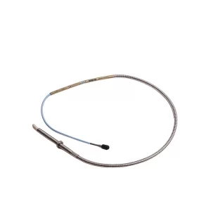
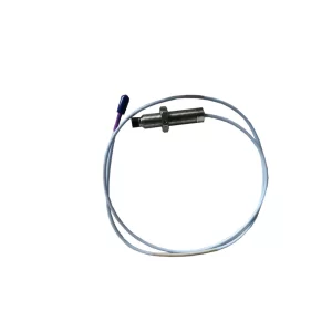
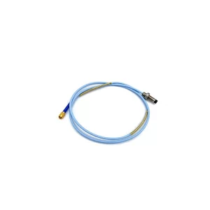
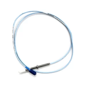
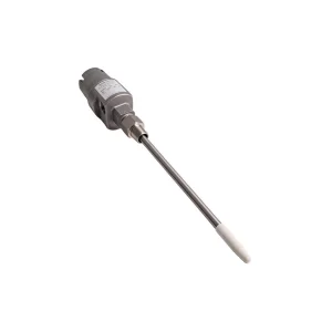
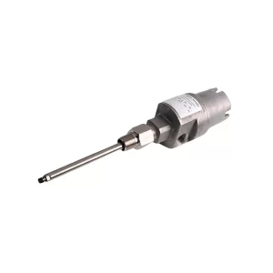
Sensor selection follows the temperature and frequency at each location. The 330400 accelerometer is the general-purpose choice for crossheads, main bearings and the transmission, rated from -55 to +121 degrees Celsius with an M8 stud mount. The 330500 Velomitor is useful where velocity is the preferred unit for lower-frequency bearing and casing measurements, also rated to +121 degrees Celsius. The 330450-20 high-temperature acceleration system is the choice near hot fluid-end or exhaust surfaces, with a 100 mV/g sensitivity, 80 g peak range, 15 Hz to 10,000 Hz band and a -40 to +482 degrees Celsius rating. For the keyphasor, a 3300 XL 8 mm proximity probe paired with the 3500/25 module is the standard combination; the 3300 XL probe and extension cable page lists the common configurations.
Installation quality decides whether the data is usable. Most of these sensors are case-mounted, so the pump needs a flat spot, a drilled and tapped hole and a spot-faced surface. Mount the crosshead accelerometer on top of the guide, close to the reversal event. Mount the fluid-end accelerometer on the back of the cylinder, as close as possible to the valves, while preserving access for valve replacement and fluid removal. Use stud mounting for permanent installations; a magnetic or adhesive mount is acceptable for a survey, not for a protection or trend channel. Keep cable runs away from high-current conductors, provide strain relief and a weatherproof junction box at the skid, and record the mounting orientation so a replacement sensor produces a comparable signal.
For the network, Bently’s pilot placed the 3500 and vbOnline hardware in a weatherproof junction box near the pump skid and connected it to the on-premises System 1 server through a wireless modem. That is a practical pattern for a mobile frac fleet. The non-negotiable parts are a stable time source, a segmented network with the monitoring traffic separated from business traffic, and a data-retention policy long enough to compare this month’s baseline with last year’s. If remote diagnostics are part of the plan, replicate the System 1 server rather than exposing the pump network directly.
3500 vs 2300/20 vs 1900/65A: right-sizing the hardware
Not every frac pump needs a full 3500 rack. The right choice depends on whether the goal is protection, crank-angle diagnostics, or simple condition trending. The table below compares the three Bently options that most often appear in these discussions.
| System | Channel capability | Best fit | Limits |
|---|---|---|---|
| 3500 VMS | Modular rack; keyphasor, 4-channel 42M monitors, transient capture, Modbus gateway, relay outputs | Critical frac pumps, fleet standardization, protection plus crank-angle impact analytics | Higher hardware and engineering cost; requires rack space and configuration |
| 2300/20 monitoring module | Two accelerometer inputs plus a dedicated speed or keyphasor input; Modbus Ethernet; local display; two relays | Smaller standalone pumps or skids where a compact, self-contained monitor is enough | Channel count is limited; not a full crank-angle analytics platform |
| 1900/65A general-purpose protection | Four configurable channels; acceleration, velocity or displacement; 4–20 mA and relays; SIL 2 | Driver or balance-of-plant protection where a compact protection path is required | No native crank-angle impact analytics; not a substitute for the 3500 analysis layer |
The 2300/20 is interesting because it includes a dedicated speed input, which means a small pump can still use a once-per-rev reference for speed-compensated trending. What it does not provide is the full multi-channel, crank-angle waveform workflow that Bently used on the frac fleet. The 1900/65A is a protection device first; it can contribute vibration data, but it should not be sold as an impact-event analyzer. The 3500 remains the appropriate choice when the requirement is protection-grade processing, keyphasor-referenced impact logic and a clear path to System 1.
The business case without invented numbers
Condition monitoring business cases fail when they start with a savings percentage instead of a cost model. A defensible calculation has five inputs: the cost of one unplanned pump failure, the number of failures avoided per year, the reduction in consumable replacement, the reduction in emergency inventory, and the installed cost of the monitoring system. The pilot supplies evidence for the first three, but the numbers are installation-specific.
| Value driver | What to count | How to estimate |
|---|---|---|
| Unplanned downtime | Hours of deferred revenue or replacement pump cost | Use the actual spread economics, not a published day rate; include mobilization and standby |
| Repair and replacement | Parts, labor, logistics and collateral damage | The pilot cites about USD 300,000 avoided on a crosshead event and about USD 100,000 on a transmission repair, both customer estimates |
| Consumables | Valves, seats, packing and labor | The pilot extended valve life by 27% and seat life by 50%; apply your own consumption and prices |
| Inventory | Safety stock and expedited freight | Count the reduction in emergency orders, not the entire warehouse value |
| HSE exposure | High-pressure release, fire and personnel risk | Use the site risk matrix; do not invent a dollar value without a documented basis |
| Monitoring cost | Sensors, racks, installation, software, network and training | Get a quote for the channel budget, including engineering and commissioning |
The formula is simple: net annual benefit equals avoided downtime plus avoided repair plus consumable savings plus inventory reduction, minus the annualized capital and operating cost of monitoring. Run it for three years with a sensitivity range on downtime and failure frequency. If the case only works at the highest assumed failure rate, the program is a bet, not a business case. The pilot’s strongest argument is not the USD 300,000 headline; it is that the crosshead impact was visible at a fixed crank angle, repeated every revolution, and gave the operator two days to plan. That is a measurable change in decision quality.
A 90-day implementation plan
- Scope the pump and the decisions, weeks 1–2. List the failure modes you intend to catch, the maintenance actions that follow, and the people who will act on the alarms. A monitoring system without a decision owner becomes a dashboard nobody uses.
- Survey the mounting locations, weeks 2–3. Confirm flat spots, temperature, access, cable routes and hazardous-area classification. Photograph each location and record the orientation. Decide whether the fluid end gets three or six accelerometers.
- Design the channel budget and network, weeks 3–4. Allocate 3500 channels for keyphasor, crossheads and fluid end; allocate vbOnline channels for main bearings, transmission and diesel. Specify time synchronization, data retention and remote access.
- Install and commission, weeks 4–8. Drill, tap and spot-face the mounting pads; install the sensors and junction box; verify cable continuity and sensor bias; confirm the keyphasor produces exactly one pulse per revolution and a stable top-dead-center reference.
- Baseline at multiple operating states, weeks 8–10. Capture data at low, medium and high pressure and at each gear used in service. Record the impact amplitude, angle and count for every cylinder. Set the initial alert and danger bands from the baseline, not from a generic vibration table.
- Validate and hand over, weeks 10–12. Compare at least one known event, such as a valve change or a planned inspection, against the data. Train the operations and maintenance team on the alarm-to-action table. Review the first month of alarms and remove any that cannot lead to an action.
The sequence matters. Teams that install sensors first and define decisions later usually end up with a system that alarms on load changes and is ignored within a quarter. Teams that define the decision first tend to install fewer channels, but every channel has a purpose.
Frequently asked questions
What is frac pump monitoring with 3500 VMS and vbOnline?
Frac pump monitoring is the continuous measurement of vibration, speed and process data on a high-pressure reciprocating pump so that developing faults are found before they stop a frac stage. In the Bently Nevada architecture, a 3500 Vibration Monitoring System handles the keyphasor plus crosshead and fluid-end accelerometers for crank-angle impact detection, while vbOnline handles main bearing, transmission and diesel motor accelerometers for rolling element and gear diagnostics. System 1 correlates both with PLC process data.
Why is a keyphasor required for impact-event detection?
A keyphasor gives one pulse per crankshaft revolution. That pulse establishes top dead center for each cylinder and lets the software place every impact in a crank-angle window. Without the reference, a short impact can be seen but not assigned to a cylinder, a stroke event or a specific mechanism. The Bently pilot used the crank-angle position to identify a crosshead impact at 40 degrees and a debris impact near top dead center.
Which frac pump signals belong on the 3500 and which on vbOnline?
The published split puts the crankshaft keyphasor, three crosshead accelerometers and the fluid-end accelerometers on the 3500 VMS, because those channels need crank-angle impact logic and protection-grade processing. Main bearing, input shaft bearing, transmission and diesel motor accelerometers go to vbOnline, where twelve simultaneous channels and spectral tools support rolling element and gear diagnostics. The split is a channel allocation decision, not a product limit; a single Orbit 60 system can host both roles in new projects.
Can vibration monitoring detect fluid-end valve and seat failures?
Yes, once the failure changes the valve opening or closing impact. Fluid-end accelerometers mounted close to the valves register those impacts in the filtered waveform. The Bently pilot detected early valve failures at 15 to 17 hours instead of the 22-hour calendar change, and extended average valve life from 22 to 28 hours and seat life from 40 to 60 hours. The method is less sensitive to early erosion that has not yet changed valve dynamics, so it complements inspection and flow or pressure data.
How does PLC data change the diagnosis?
PLC data supplies the operating state: discharge pressure, suction pressure, flow, engine speed, gear selection and lube oil condition. A vibration rise at constant speed and pressure points to a mechanical fault, while a rise that tracks pressure or gear selection points to a load or operating condition. In the Bently installation, PLC data arrived over Modbus or OPC and engine data over a CAN converter, allowing state-based thresholds instead of one fixed alarm level.
Is vbOnline a protection system?
No. vbOnline is an online condition monitoring device. It trends and analyzes vibration for diagnostics, but it is not the relay-based trip path for the pump. Machinery protection, where required, stays in the 3500 or another protection system with relay outputs and the appropriate safety rating. The two roles should be specified separately even when they share a network and a System 1 server.
What sample rate and sensor bandwidth are needed for impact detection?
The published pilot filtered crosshead vibration from 3 Hz to 2,000 Hz and used zero-to-peak amplitudes. That band is enough to separate rod reversal and valve impacts from low-frequency running vibration, but it is not a universal answer. Valve and debris impacts contain higher frequencies, so confirm the measurement band of the exact 3500 module and use transient or high-rate capture where the waveform detail matters. The 3500/22M Transient Data Interface can capture triggered waveforms at up to 1 Msample per second.
Can condition-based maintenance replace all time-based maintenance on a frac pump?
No. The pilot replaced calendar-based valve and seat changes with condition-based decisions and extended component life, but it did not eliminate inspections, lubrication tasks or safety checks. Some failure modes, including fluid-end block cracks and internal erosion before impact changes, remain weakly observable. A practical program keeps a maximum interval as a backstop, uses condition data to shorten or extend it, and reserves immediate shutdown for clear impact or process anomalies.
Related reading
- Natref refinery reciprocating compressor case study: 3500 and System 1 — a different reciprocating machine with the same phase-referenced monitoring logic.
- Bently Nevada 3500 support status and the Orbit 60 transition — lifecycle planning for an installed 3500 fleet.
- 3500 spares planning for RoHS and PCBA refresh — the procurement side of keeping a 3500 rack in service.
- 3500 PCBA refresh and long-term support — what to verify before a module is repaired or replaced.
- System 1 at 20 years and 10,000 users — the software layer that turns these channels into decisions.
- Bently Nevada applications for oil and gas compressors and petrochemical protection — adjacent duty cycles and monitoring requirements.
- Orbit 60 input and output card update — the consolidation path for new projects.
Sources and method
This article is built from Bently Nevada’s published Orbit article on reciprocating pump condition monitoring, the 3500 and Orbit 60 product documentation, the relevant API standards and the product specifications linked above. The sensor counts, filter band, crank-angle findings, pilot intervals and savings figures are attributed to Bently’s article. The channel budget, the coverage ratings, the decision-rule table and the business-case framework are TenBN editorial analysis, not vendor claims.
- Bently Nevada, “Reciprocating Pumps Condition Monitoring,” Orbit article — primary source for the architecture, pilot installation and case results.
- Bently Nevada, 3500 Machinery Protection Systems — platform and module overview.
- Bently Nevada, Orbit 60 Series — the consolidated platform referenced for new projects.
- Bently Nevada, “Trendmaster and its new Software” — confirms the 12-channel vbOnline Pro and its place in a tiered monitoring architecture.
- API Std 674, Positive Displacement Pumps — Reciprocating, third edition, 2010, reaffirmed 2016 — scope and design basis for reciprocating pumps in petroleum, petrochemical and natural gas service.
- API Std 670, Machinery Protection Systems — the protection-system reference commonly applied to the transmission and driver measurements.
Editorial note: the pilot is a single installation in Latin America, and the savings are customer-reported. Component life and maintenance-cost improvements depend on duty, fluid chemistry, operating practice and the quality of the baseline. Confirm current module specifications, certifications and lifecycle status against the latest Bently Nevada datasheet and your bill of materials before purchase. This article is not a substitute for a machinery protection review or an OEM commissioning procedure.