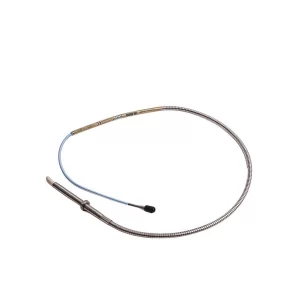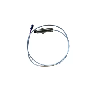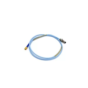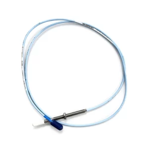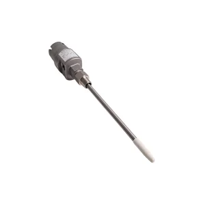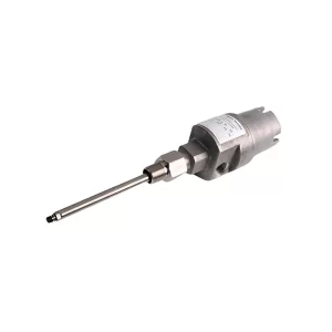

Bently Nevada’s Ranger Pro is a battery-powered wireless vibration sensor that reports 16 measurements per sensor: velocity on three axes, acceleration on three axes, Z-axis PeakDemod, temperature and battery level, counted across both overall and waveform/spectrum data. It runs on either ISA100.11a or WirelessHART, encrypts packets with 128-bit AES, carries an IP67 rating and operates from -40 °C to +85 °C. The datasheet range is 150 m from sensor to access point and 100 m from sensor to sensor, line of sight. The replaceable D-size lithium thionyl chloride battery is rated up to five years, but temperature and data interval decide whether you actually get there.
By TenBN Editorial Team · Updated November 2, 2026 · 15 minute read
Quick answer
The Ranger Pro is the right tool when a machine has rolling-element bearings, sits in a hazardous or hard-to-reach area, and does not justify a wired monitoring channel. It is not a machinery protection system: it has no trip outputs, no API 670 role and no keyphasor input. It is a condition-monitoring sensor that turns a monthly portable route into a continuous trend, with enough spectral data to diagnose a bearing defect rather than only detect that vibration rose.
Three details in the headline specification deserve a closer look before you standardize on it. The 16 measurements are 16 data products from nine channels, not 16 independent sensing points. The 10 kHz acceleration limit applies to the Z axis only; X and Y stop at 4 kHz. And 100 m is the sensor-to-sensor routing distance, not the distance to the gateway, which is 150 m under line of sight. Those distinctions change mounting, network design and the assets you assign to wireless.
Specifications at a glance
| Parameter | Ranger Pro value | What it means in practice |
|---|---|---|
| Measurements | 16 per sensor (nine channels: velocity X/Y/Z, acceleration X/Y/Z, PeakDemod Z, temperature, battery) | Overall plus waveform/spectrum data products on the same axes |
| Acceleration range | Z 5 Hz to 10 kHz; X/Y 5 Hz to 4 kHz | Only the Z axis reaches gear-mesh and high-frequency bearing tones |
| Velocity range | 5 Hz to 2000 Hz on all three axes | Covers the ISO 20816-3 evaluation band for machines above 15 kW |
| Amplitude | ±20 g peak; 0 to 50 mm/s | Sufficient for most motors, fans, blowers and pumps |
| Accuracy | ±5% Z, ±10% X/Y at 160 Hz | Trend change matters more than absolute accuracy |
| Temperature | -40 °C to 120 °C sensing range, 0.1 °C resolution | Reads the sensor base, not the bearing metal |
| Operating temperature | -40 °C to +85 °C | Battery chemistry narrows the real ceiling |
| Security | 128-bit AES encrypted packets | Link-layer encryption; plant segmentation is still required |
| Environmental | IP67, 316 stainless steel body, PPS top, 0.5 m drop | Washdown and outdoor mounting are possible with the right adapter |
| Wireless range | 150 m to access point; 100 m sensor to sensor, line of sight | Routing distance, not a plant-wide coverage claim |
| Battery | Replaceable D-size 3.6 V lithium thionyl chloride, up to five years | Life depends on interval, temperature and waveform settings |
| Size and weight | 88 mm high, 40 mm diameter; 230 g without battery, 300 g with | Small enough for tight motor and fan housings |
The 16 measurements, deconstructed
Bently Nevada’s own product page states that overall and waveform/spectrum data can be collected from all three axes in velocity and acceleration, plus peak demodulation on the Z axis, along with temperature and battery level, and that this “equates to 16 measurements from each sensor.” The datasheet lists nine channels. The difference is not marketing arithmetic for its own sake: it reflects that each axis produces an overall value and a spectral or waveform product, and that PeakDemod, temperature and battery status are separate outputs.
| Channel | Axes | Frequency range | Data products |
|---|---|---|---|
| Velocity | X, Y, Z | 5 to 2000 Hz | Overall RMS or peak; velocity spectra |
| Acceleration | X, Y, Z | Z: 5 Hz to 10 kHz; X/Y: 5 Hz to 4 kHz | Overall RMS or peak; acceleration spectra and waveforms |
| PeakDemod | Z only | Fmax 200 to 5000 Hz; demod band from 500, 1000, 2000 or 5000 Hz | Overall PeakDemod; PeakDemod spectrum or waveform |
| Temperature | Integral sensor | Not applicable | Overall value, 0.1 °C resolution |
| Battery level | Integral | Not applicable | Status value for sensor readiness |
The practical consequence is simple. A triaxial Ranger Pro covers one bearing housing, not three separate machines. Mounting location still decides what the data can diagnose: a sensor on a flexible guard or a thin fan shroud will report the guard’s resonance, no matter how many channels it transmits. The 16-measurement count is a statement about data richness per location, not about coverage per sensor.
Frequency coverage: where the axes differ
Velocity is uniform across the three axes at 5 to 2000 Hz. Acceleration is not. The Z axis reaches 10 kHz, while X and Y stop at 4 kHz. That asymmetry is the most common source of confusion when a Ranger Pro is compared with a wired accelerometer, and it should drive orientation decisions.
For a horizontal motor, the highest-frequency bearing or gear-mesh energy usually travels along the radial path that the Z axis sees when the sensor is mounted vertically on the housing. If the sensor is mounted sideways so that Z points horizontally, the 10 kHz capability is spent on the horizontal direction and the vertical direction is limited to 4 kHz. On a cooling tower fan gearbox, the same logic applies: put Z on the path with the shortest, stiffest route to the bearing that worries you most.
Velocity at 5 to 2000 Hz is the band used for ISO 20816-3 evaluation of industrial machines above 15 kW. If the goal is a trend that can be compared with acceptance criteria or with a portable route, velocity overall is the number to trend. If the goal is early bearing detection, acceleration and PeakDemod carry the signal, and the Z-axis limit becomes the constraint to design around. On a wired machine, the equivalent velocity signal comes from a 330500 Velomitor; keeping the wireless and wired trends on the same units makes the transition between tiers easier.
PeakDemod: the Z-axis measurement that earns its place
PeakDemod is a demodulated acceleration measurement: the high-frequency carrier produced by a rolling-element defect is extracted, and its repetition rate is presented in the spectrum. On the Ranger Pro it is available on the Z axis only, with an Fmax from 200 to 5000 Hz and a demodulation band that starts at 500, 1000, 2000 or 5000 Hz.
That single channel is often what separates a wireless sensor from a vibration switch. A switch tells you that overall vibration crossed a level. PeakDemod, trended over months, tells you whether the bearing condition is degrading while the overall velocity is still inside the acceptance band. For low- and medium-criticality machines, that is the difference between planning a bearing change and reacting to a seized fan.
The Z-only limitation is a design trade-off, not an oversight. Running demodulation on three axes would increase processing, radio payload and battery drain. If triaxial demodulation is mandatory, the wired route is a 330400 accelerometer into a monitor with demodulation, or a 3500/42M channel. For everything below that threshold, one well-oriented Z axis is a reasonable compromise.
ISA100.11a vs WirelessHART: same sensor, different plant
The Ranger Pro is sold in both protocol families. The measurement hardware is the same; the part number, gateway ecosystem and integration path change. The choice should be made from the plant’s existing wireless infrastructure and control system, not from the sensor datasheet.
| Item | ISA100.11a | WirelessHART |
|---|---|---|
| Sensor part numbers | 70M303 triaxial; 70M301 uniaxial | 70M403 triaxial only |
| Radio | IEEE 802.15.4, 2.45 GHz ISM | IEEE 802.15.4, 2.45 GHz ISM |
| Topology | Star or mesh | Mesh |
| Bently gateway | 70M320, up to 50 Ranger Pro devices | No Bently gateway; Emerson 1410S, 1410 or 1420 |
| Integration to System 1 | Generic Client Interface (GCI) | HART-IP |
| Repeater | Ranger Pro repeater, 70M300 | Routes through other WirelessHART devices |
| Best fit | Plants already running ISA100 with Yokogawa or Honeywell gateways | Plants with an Emerson WirelessHART backbone or HART-IP infrastructure |
Two consequences follow. First, the uniaxial option exists only in the ISA100 family: if a location needs a single axis to save cost, the protocol decision is already made. Second, the gateway capacity is not the same: a Bently 70M320 supports 50 sensors, while an Emerson 1410S supports up to 200. That difference matters when a pilot grows from ten sensors to a full unit.
Both families use 128-bit AES encrypted packets at the link layer. That protects the air interface; it does not replace network segmentation, gateway hardening or a patching process. Treat the wireless network as an industrial control network with its own security policy, not as an extension of the office Wi-Fi.
Gateways, repeaters and the three-hop ceiling
Ranger Pro devices route through each other. The datasheet limits the network to three hops from sensor to gateway, which makes physical layout a first-order design task. A sensor at the far end of a long conveyor gallery may be within radio range of the gateway and still fail the hop limit if every path crosses four other devices.
| Gateway | Protocol | Ranger Pro capacity | Notes |
|---|---|---|---|
| Bently Nevada 70M320 | ISA100.11a | Up to 50 devices | Native path to System 1 through GCI |
| Yokogawa YFGW410 | ISA100.11a | Up to 4 access points, 160 sensors | 40 sensors per YFGW510 or YFGW520 access point |
| Honeywell WDM | ISA100.11a | Up to 8 access points, 320 sensors | Requires WDM R310.2-4 or newer; FDAP supports 40 per access point |
| Emerson 1410S | WirelessHART | Up to 200 sensors | Firmware 6.4.5 or newer |
| Emerson 1410 and 1420 | WirelessHART | Up to 70 sensors | Firmware 4.7.84 or newer |
Data leaves the system on two paths. Overall values are available through Modbus from the device gateway, which is enough for a DCS trend or a historian tag; on the wired side, the equivalent path is the 3500/92 communication gateway. Waveforms and spectra require Generic Client Interface for ISA100 devices or HART-IP for WirelessHART devices, and land in System 1 v20.2 or higher. A System 1 Ranger Pro device license (3071/13) is required for each sensor used with System 1. Plan the licensing and the gateway firmware before the first sensor is powered, because both are procurement items with lead time.
What 100 m and 150 m mean in a real plant
The datasheet gives two distances: 150 m from sensor to access point and 100 m from sensor to sensor, both line of sight. The shorter number is the routing budget. Once sensors relay through each other, each link must close at 100 m, and the path must stay within three hops.
Line of sight is a stricter condition than it sounds in a plant. A steel-clad wall, a dense pipe rack, a large motor or a filled silo will absorb or reflect 2.45 GHz energy. So will a sensor mounted flat against a hot surface with its antenna facing the wrong way. The datasheet notes that actual range depends on obstacles, gateway antenna type and sensor orientation. A site walk with a temporary gateway is cheaper than discovering the problem after commissioning.
Coexistence is the second issue. The 2.45 GHz band is shared with Wi-Fi, cordless phones and other wireless systems. A plant with strong Wi-Fi coverage in the same area is not automatically a good ISA100 site; the two networks can interfere even though both are IEEE 802.15.4-adjacent in frequency. Include a spectrum check in the survey, and keep the wireless gateway off the office network segment.
Battery life is a configuration decision
The headline is up to five years. The real number is a function of how often the sensor reports overall values, how often it captures spectra or waveforms, how many hops it relays for other sensors, and how warm it runs. Overall intervals range from 10 minutes to 6 hours; waveform and spectrum intervals range from 6 hours to 28 days. A sensor reporting overall every 10 minutes and spectra daily will not reach five years.
Temperature is the harder constraint. The sensor is rated to +85 °C operating, but the approved batteries derate below that: the Tadiran TLH-5930 is limited to 80 °C ambient, while the TL-5930, SL-2780 and Xeno XL-205F are limited to 70 °C. The temperature sensing range extends to 120 °C, which is useful for trending, but it does not change the battery ceiling.
| Battery | Maximum ambient | Note |
|---|---|---|
| Tadiran TLH-5930 | 80 °C | Highest-temperature approved option |
| Tadiran TL-5930 | 70 °C | Standard option |
| Tadiran SL-2780 | 70 °C | Standard option |
| Xeno Energy XL-205F | 70 °C | Standard option |
Use the advanced modes to protect the budget. Data on demand lets an analyst request a reading instead of waiting for the next interval. Data on vibration acquisition triggers collection only when the machine is running, using a threshold between 0 and 0.1 in/s RMS, with detection by XYZ vector sum or Z axis. Data on severity adds green, yellow and red states at user-set levels between 0.05 and 2.5 in/s RMS, and a separate temperature severity range from 0 to 125 °C. These modes cut the number of transmissions on machines that run intermittently, which is where wireless batteries usually die early.
The battery is a replaceable D-size 3.6 V lithium thionyl chloride cell with standard button-top termination. Approved models are the four listed above; substituting an unapproved cell voids the hazardous-area approval. The sensor can be ordered with the battery supplied but not installed, and the installation kit (130M5452) includes the battery tool, O-rings and wrenches. Replacement is a field task, not a factory return, which is one of the practical advantages over sealed wireless sensors.
The environmental envelope: IP67, Zone 0 and -40 to +85 °C
The Ranger Pro carries global hazardous-area approvals: Class I Zone 0, Class I Division 1, ATEX and IECEx ia, plus dust ratings for Zone 20 and Class II Division 1. That matters because the assets that most need wireless monitoring are often the ones in classified areas where running conduit is expensive or impossible.
The mechanical package is built for the same environment: 316 stainless steel body, glass-reinforced PPS top, IP67 sealing, a 0.5 m drop rating onto concrete, a 20 g vibration limit and a maximum altitude of 3000 m outdoors. The mounting thread is M6 x 1 mm, 5 mm deep, with stud adapters, a magnetic mount and epoxy cementing pads available. The magnetic mount is convenient for a survey and a poor choice for a permanent installation on a high-speed machine.
Read the approvals as a system, not a sensor. The certificate covers the approved part number with an approved battery; a third-party cell or an unlisted adapter changes the assembly. In a Zone 0 area, that is an engineering change, not a consumable swap.
Where wireless belongs: tiering with wired hardware
Wireless sensors are not a cheaper version of a 3500 rack. They cover a different tier of assets, and the program works best when the tiers are explicit.
| Asset tier | Typical hardware | Why |
|---|---|---|
| High criticality: main turbines, critical compressors, machines with trip logic | 3500 system with proximity probes, 3500/25 keyphasor and 3500/42M channels | Protection, API 670 role, keyphasor and hardwired trips |
| Medium criticality, accessible, wired power available | 1900/65A or 2300/20 | Continuous monitoring at lower installed cost than a rack |
| Low and medium criticality, remote, hazardous or hard to wire | Ranger Pro, triaxial where the geometry allows | No conduit, no local power, battery life measured in years |
| Sleeve-bearing turbomachinery | 3300 XL 8 mm or 3300 XL 11 mm probes with 3500 monitors | Ranger Pro is specified for rolling-element bearing machines |
| Machines visited on a route | Portable collector | Ranger Pro replaces the route, not the analyst |
The datasheet’s machinery list is explicit: agitators, air compressors, ball mills, blowers, centrifuges, cooling tower fans and pumps, motors, small reciprocating compressors, and small hydro and steam turbines, all with rolling-element bearings. For sleeve-bearing machines, the wireless accelerometer sees the housing but not the oil-film dynamics that proximity probes measure. Do not use it as a substitute for a Velomitor CT or a proximity probe on a machine where shaft-relative vibration is the protection variable.
Wireless is also a good fit for the balance of plant that never had monitoring: cooling water pumps, closed cooling water fans, instrument air compressors, and the small motors that fill a cooling and HVAC or paper mill balance of plant. The same logic applies to the auxiliary trains around a gas turbine or a gas compressor package. These assets are individually low value and collectively responsible for a large share of unplanned downtime.
Wireless changes how data reaches the monitoring network; it does not change the segregation rule. A Ranger Pro gateway still lands on the condition monitoring side of the architecture, so the trip path is only as protected as your zone and conduit design. For the rack-side counterpart to that decision, see what “designed to SL4” commits Orbit 60 to, and what is actually certified.
A 90-day deployment plan
| Phase | Timing | Output |
|---|---|---|
| Asset and RF survey | Weeks 1 to 2 | Asset list ranked by criticality; spectrum sweep; candidate gateway and repeater locations |
| Protocol and gateway decision | Weeks 3 to 4 | ISA100 or WirelessHART; gateway model and firmware; System 1 licensing |
| Pilot install | Weeks 5 to 6 | Ten to twenty sensors on two machine trains; mounting and antenna orientation verified |
| Baseline and alarm design | Weeks 7 to 8 | Four to six weeks of baseline; velocity, acceleration and PeakDemod thresholds; temperature severity |
| Scale and workflow | Weeks 9 to 12 | Remaining sensors; route-to-wireless transition; analyst ownership and escalation path |
The baseline phase is not optional. A wireless sensor installed on a machine with no history produces an alarm on day one that nobody can interpret. Four to six weeks of data at the production interval establishes the normal scatter band and the seasonal effects, which is what makes a later threshold meaningful.
Common mistakes
| Mistake | What happens | Fix |
|---|---|---|
| Reading 16 measurements as 16 sensing points | Coverage is overestimated and machines are missed | Count one triaxial sensor per bearing housing; use the channel table above |
| Mounting on a guard, shroud or flexible bracket | The trend reflects the bracket, not the bearing | Mount on a rigid, machined surface close to the bearing load zone |
| Ignoring battery temperature limits | Premature battery failure and lost data | Check ambient against the 70 °C or 80 °C cell limit, not the 85 °C sensor limit |
| Choosing the protocol after buying sensors | Gateways and licenses do not match the installed base | Decide gateway and protocol first; uniaxial exists only in ISA100 |
| Assuming Wi-Fi coverage equals ISA100 coverage | Links drop at the far end of the unit | Run an RF survey and respect the three-hop limit and the 100 m routing distance |
| Using wireless for protection | No trip, no keyphasor, no API 670 compliance | Keep protection on the 3500 or a 1900/65A; use wireless for condition monitoring |
Frequently asked questions
What are the 16 measurements on the Ranger Pro?
Bently Nevada counts 16 measurements per sensor: velocity on X, Y and Z; acceleration on X, Y and Z; Z-axis PeakDemod; temperature; and battery level, with overall and waveform/spectrum data collected across those channels. The datasheet lists nine physical channels, so the 16 figure reflects data products as well as axes.
Does the Ranger Pro support both ISA100.11a and WirelessHART?
Yes, but not in the same unit. The ISA100.11a versions are 70M303 (triaxial) and 70M301 (uniaxial); the WirelessHART version is 70M403 (triaxial only). The protocol is fixed at order and determines which gateways and integration path are available.
What is the Ranger Pro wireless range?
The datasheet specifies 150 m from sensor to access point and 100 m from sensor to sensor, both line of sight. Obstacles, antenna type and sensor orientation reduce the real range, and the network is limited to three hops from sensor to gateway.
What frequency ranges does the Ranger Pro measure?
Velocity covers 5 to 2000 Hz on all three axes. Acceleration covers 5 Hz to 10 kHz on the Z axis but only 5 Hz to 4 kHz on X and Y. PeakDemod is Z-axis only, with an Fmax from 200 to 5000 Hz and a demodulation band starting at 500, 1000, 2000 or 5000 Hz.
How long does the Ranger Pro battery last, and can it be replaced?
The replaceable D-size 3.6 V lithium thionyl chloride battery is rated up to five years, depending on data interval, waveform settings, routing load and temperature. Approved cells include the Tadiran TLH-5930, TL-5930, SL-2780 and Xeno XL-205F, with ambient limits of 80 °C and 70 °C respectively.
Can the Ranger Pro be used in hazardous areas?
Yes. Approved versions carry Class I Zone 0, Class I Division 1, ATEX and IECEx ia approvals, plus dust ratings for Zone 20 and Class II Division 1. The approval applies to the approved part number with an approved battery, so substitutions change the certification.
Is the Ranger Pro a replacement for a 3500 monitoring system?
No. It has no trip outputs, no keyphasor input and no API 670 protection role. It is a condition-monitoring sensor for rolling-element bearing machines, best used for low- and medium-criticality assets that cannot justify a wired channel.
What software and gateways are needed for Ranger Pro?
ISA100 devices use a Bently Nevada 70M320, Yokogawa or Honeywell gateway with Generic Client Interface into System 1 v20.2 or higher. WirelessHART devices use an Emerson 1410S, 1410 or 1420 gateway with HART-IP. Overall values are also available through Modbus at the gateway. A System 1 device license is required per sensor.
Related reading
- Cordant Devices: what the Bently Nevada homepage change means for spares buyers
- Orbit 60 fact sheet: 100x processing, 65 channels and half the footprint
- Cooling tower fan monitoring: the $300K case for permanent systems
- Frac pump monitoring: 3500 VMS and vbOnline impact-event detection
- Bently Nevada 3500 spares planning 2026: support, RoHS boards and what to stock
Sources and method
Specifications in this article come from the Bently Nevada Ranger Pro Wireless Condition Monitoring datasheet, document 125M5237 Rev. V, and the Ranger Pro fact sheet GEA34045A. The 16-measurement statement is quoted from the Ranger Pro product page on bakerhughes.com. Where the marketing count and the datasheet channel list differ, both are shown and the difference is explained rather than resolved in favor of the larger number.
Three boundaries are worth stating. First, the datasheet range figures are line-of-sight values; no site-specific RF survey result is published, so actual coverage must be measured. Second, battery life is configuration-dependent and the five-year figure is a maximum, not a typical value. Third, the accurate acceleration limit for X and Y is 4 kHz, not 10 kHz; any specification that assigns 10 kHz to all three axes is overstating the horizontal and vertical coverage.
Reference documents: