
TL;DR
- Both sensors are 2-pin, not 3-pin. The 330500 uses a 2-pin MIL-C-5015 receptacle; the 330525 uses a 2-pin MIL-C-26482. The familiar 3-pin MIL-C-5015 belongs to the 330400/330425 accelerometers, which is where the confusion usually starts.
- Electrically they are close twins: same 3.94 mV/mm/s (100 mV/in/s) ±5% sensitivity, same −55 °C to +121 °C range, same 316L stainless case, same case-isolated grounding, same two-wire constant-current interface. The one real difference is bandwidth — 5 kHz for the 330500, 2 kHz for the 330525.
- Neither needs an external charge amplifier. Both amplify and integrate inside the housing and present a low-impedance voltage proportional to velocity. The 330400/330425 do not need one either — they also contain internal charge amplifiers, powered by −24 VDC.
- 305 m (1,000 ft) is the published maximum, and it is cable-specific: P/N 02173006 for the 330500, 02173007 for the 330525. The same datasheet also prints a recommended length of 63 m (208 ft) for the worst case of 50 g at 10 kHz on 200 pF/m cable.
- Immunity is a wiring discipline, not a sensor property. The case is isolated by design, the shield is bonded at the sensor connector, and the plant side has to keep that shield single-pointed.
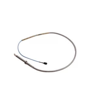
- 330525 means XA — eXtended Application: weatherproof connector and cable assembly, IP-65/NEMA 4X with a mating extension cable, 1/4-18 NPT base, mounted without a housing.
What is a Velomitor, exactly?
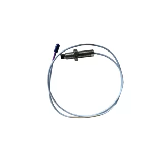
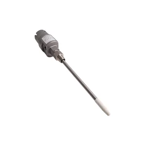
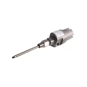
A Velomitor is a piezoelectric accelerometer with the integration already done inside the housing. The sensing element is a shear-mode piezoelectric ceramic; the electronics amplify the charge and integrate it once, so the output is a voltage proportional to velocity rather than acceleration. Bently Nevada’s own user guide puts it plainly: “The sensor internally amplifies and integrates this signal to produce a low-noise output signal that is proportional to velocity.”
That single design decision explains most of what follows. Velocity is the natural unit for the ISO-style casing criteria used on pumps, motors, compressors and fans, and it is the unit most rotating-equipment engineers still reason in. A moving-coil velocity transducer produces velocity natively but wears out, because it has a coil, a magnet and relative motion. The Velomitor gets to the same unit with no moving parts, which is why the datasheet can promise a 5,000 g shock survival and a service life measured in years rather than in coils.
The trade-off is bandwidth. Integration rolls off the high end, and a piezo-velocity sensor is a bearing-housing and casing device, not a gear-mesh device. If you are chasing a 3 kHz gear mesh sideband, you want acceleration, not velocity. That distinction matters later when we compare the family.
Are the 330500 and 330525 2-pin or 3-pin?
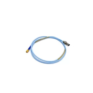
Both are 2-pin. The 330500 datasheet specifies a “2-pin Mil-C-5015 hermetically-sealed, 316L stainless steel shell” connector, and the dimensional drawing labels it “2-pin, MIL-C-5015 receptacle”. The 330525 moves to a different shell standard — “2-pin Mil-C-26482 hermetically-sealed, 316L stainless steel shell” — because its connector is part of the weatherproof cable assembly rather than a plain receptacle.
So where does the 3-pin story come from? From the accelerometers. The 330400 and 330425 are built on a “3-pin MIL-C-5015 Receptacle 316L stainless steel”, and Bently Nevada’s Orbit article on accelerometer construction explains why: those two models were designed as drop-in replacements for 1980s three-wire systems that ran power, signal and common separately, and they “do not require external interface modules or special coaxial cable” but “retain a 3-wire design”. The 3-pin MIL-C-5015 is a real Bently Nevada connector — it just is not the Velomitor one.
The pin count follows the electrical architecture. A Velomitor is a two-wire device: DC bias and AC signal share the same pair between Pin A and Pin B, which is why the polarity note in both datasheets is written as “Pin A goes positive with respect to pin B” rather than as a three-terminal reference. Adding a third pin would buy nothing on a constant-current sensor and would break compatibility with the 3500/42 Prox/Velom I/O and 3300/55 dual velocity monitor inputs the sensor was designed around.
| Item | 330500 | 330525 | 330400 / 330425 |
|---|---|---|---|
| Connector | 2-pin MIL-C-5015, hermetic | 2-pin MIL-C-26482, hermetic | 3-pin MIL-C-5015 |
| Output quantity | Velocity | Velocity | Acceleration |
| Wiring | 2-wire, constant current | 2-wire, constant current | 3-wire (PWR / SIG / COM) |
| Excitation | 22–30 VDC, 2.5–6 mA via constant-current diode | −22 to −30 VDC, 2.5–6.0 mA | −24 ±0.5 VDC, 2 mA nominal |
| Mounting | 3/8-24 UNF internal + adapter stud | 1/4-18 NPT external thread | Integral 1/4-28 UNF or M8 stud, in a housing |
330500 vs 330525: what actually differs?
Less than the model numbers suggest, and the differences are engineering ones rather than performance ones. The 330525 datasheet calls itself “a ruggedized version of Bently Nevada’s 330500 Velomitor Sensor”, and the numbers agree on everything that matters for signal quality: the same calibrated sensitivity, the same 1,270 mm/s (50 in/s) peak velocity range, the same ±2% linearity to 152 mm/s, the same 0.004 mm/s (160 µin/s) rms noise floor, the same −12 ±3 VDC bias and sub-2,400 Ω dynamic output impedance.
| Parameter | 330500 Velomitor | 330525 Velomitor XA |
|---|---|---|
| Sensitivity | 3.94 mV/mm/s (100 mV/in/s) ±5% | 3.94 mV/mm/s (100 mV/in/s) ±5% |
| Frequency response | 4.5 Hz–5 kHz ±3.0 dB; 6 Hz–2.5 kHz ±0.9 dB | 4.5 Hz–2 kHz ±3.0 dB; 6 Hz–1 kHz ±0.9 dB |
| Operating temperature | −55 °C to +121 °C | −55 °C to +121 °C |
| Case material | 316L stainless steel | 316L stainless steel |
| Sealing | Hermetically sealed; 100% RH, non-submerged | Hermetically sealed; IP-65 and NEMA 4X with mating extension cable |
| Housing needed | Recommended in corrosive, wet or impact-prone areas (P/N 21128) | No — designed for exposed mounting |
| Mounting torque | 32–46 kg·cm (24–40 in-lb) max | 45 N·m (33 ft-lb) max |
| Mass / size | 142 g; 25.3 mm dia × 63.2 mm | 156 g; 28 mm dia × 73.1 mm |
| Integral cable | No — separate connector and cable assembly | Captive cable assembly (106765, 1–25 m), terminated in a housing |
The bandwidth gap is the item to read twice. On a 3,600 rpm machine, 1× runs at 60 Hz and even a 2 kHz ceiling covers 33 harmonics — plenty for unbalance, misalignment and bearing tones. On a 1,800 rpm motor driving a two-stage gearbox with 40-tooth pinions, the mesh sits well above 2 kHz and the 330525 will simply not see it. The 330500 at 5 kHz reaches most of that content but still truncates the upper sidebands; that is the honest boundary between a velocity sensor and an acceleration sensor, and it is why the 330400 family exists at all.
The second difference is mechanical. The 330525’s base is a 1/4-18 NPT external thread, so it screws directly into a tapped boss and needs no adapter and no housing — the reason Bently Nevada notes that “for 1/4-18 NPT mounting, order 330525” in the 330500 ordering table. That saves a housing and a bracket, but it also means the sensor is exposed, which is exactly why its connector had to become a weatherproof cable assembly with a splash boot, clamps and a 1.5-inch minimum bend radius.
Do Velomitor sensors need an external charge amplifier?
No — and neither do the 330400/330425. This is the most commonly mis-stated comparison in the family, so it is worth being precise about what is inside each housing.
A bare piezoelectric element produces charge, typically quoted in pC/g, at very high impedance. Turning that into something a monitor can read requires a charge-to-voltage conversion. Bently Nevada’s Orbit article on accelerometer construction describes the two routes: “either through the use of an external device (usually called a charge amplifier) or via integral electronics inside the accelerometer housing.” The Velomitor takes the second route. The user guide for the family says the sensor “internally amplifies and integrates this signal”, and the datasheet describes a design that “incorporates embedded integrated electronics in a solid-state design” with an output impedance under 2,400 Ω.
The 330400 and 330425 take the same route. Baker Hughes’ product page states that they “require −24 Vdc to power the internal charge amplifiers”, which is the opposite of needing an external one. Anyone repeating “Velomitor has integral electronics, 330400 needs a charge amp” has the mechanism backwards; both are voltage-output sensors, and the difference is the measured quantity and the three-wire legacy interface, not the presence of a charge amplifier.
What the Velomitor does need is excitation. The user guide is explicit: “The Velomitor Sensor is a two-wire device that requires an external power supply. The power supply must provide a DC voltage of 22 to 30 Volts and a current of 10 mA. A constant current diode must be used to limit the current to the sensor to 2.5 to 6 mA.” It then adds the sentence that matters for retrofits: “Compatible Bently Nevada monitoring systems provide the power required by the Velomitor Sensor without the need for additional external circuitry.” Feed it from a 3500/42 Prox/Velom channel or a 3300/55 and the loop is complete; wire it into a charge-amplifier input and you have a sensor that draws current and produces nothing usable.
The sensors that genuinely depend on a separate charge amplifier are the high-temperature ones. The 330900 HTVAS and the 330750 HTVS separate the sensing element from the electronics because the charge amplifier cannot survive the surface temperature, and the 350501 charge amplifier with a 45357-01 element is the same idea in component form. Those are the exceptions that prove the rule: integral electronics are the norm everywhere the housing stays below roughly 120 °C, and the Velomitor sits comfortably inside that envelope.
How long can the cable actually be?
305 m (1,000 ft), on a specified cable. Both datasheets print that figure. The 330500 wording is “305 m (1,000 ft) of cable, part number 02173006, with no degradation of signal”; the 330525 says “305 metres (1,000 feet) of cable, BN part number 02173007 with no degradation of signal.” The cable is part of the specification, not an accessory: 02173006 is two-conductor 18 AWG twisted, shielded bulk cable, while 02173007 is the 22 AWG two-conductor twisted, shielded equivalent for the XA.
There are two practical qualifications that the headline number hides.
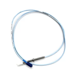
The first is the 330525’s own cable assembly. The captive interconnect cable, P/N 106765-AA, is ordered from 1 m to 25 m in 3 m increments and terminates in a terminal housing (106769-AA) with ½-inch or ¾-inch NPT fitting options. The 305 m figure is the run from that terminal housing onward using 02173007 bulk cable. A 60 m pull does not exist as a single XA assembly, and ordering one is not possible.
The second is frequency. The 330500 datasheet carries a second line that most summaries omit: “Recommended cable length (assuming max vibration of 50g, frequency 10 kHz, and cable capacitance 200 pf/m.) — 208 ft (63 m). For longer lengths, contact Bently Nevada Tech Support.” That is not a contradiction of the 305 m limit; it is the same limit stated under the harshest signal conditions Bently expects you to encounter. The source impedance of the sensor output and the capacitance of the cable form a low-pass filter, and 305 m of 200 pF/m cable is roughly 61 nF hanging on that output. At low frequencies the effect is negligible — which is why the plain 305 m claim holds for normal casing vibration — but at 10 kHz with a 50 g signal the attenuation and phase shift become large enough that Bently publishes a shorter recommended length.
Read together, the rule is: 305 m is the maximum for design purposes on a pump or fan, and 63 m is the length to design to if the measurement has to be trustworthy at kilohertz frequencies. If your run is longer than 63 m and the machine has gear mesh or blade-pass content you care about, that is a conversation with Bently tech support, not a decision to make from a datasheet headline.
Where does electrical interference actually get into the measurement?
Not through the sensing element. A shear-mode ceramic in a sealed stainless housing is about as immune as a transducer gets, and the datasheet quantifies it: magnetic field susceptibility below 51 µin/s per gauss in a 50 gauss, 50–60 Hz field, base strain sensitivity of 0.005 in/s per µstrain, and transverse sensitivity under 5% of axial. The claims are backed by an EMC Directive 2014/30/EU declaration and FCC Part 15 compliance, which is a statement about emissions and immunity of the device, not about your installation.
Interference gets in through the cable, the shield and the ground path — three things the sensor can only partly control.
Case isolation is the foundation. Both datasheets list “Grounding: Case isolated”, which means the housing is not bonded to Pin B. That is deliberate: it lets the installer decide where the measurement circuit references to earth instead of forcing a bond at the machine frame, where welding currents, VFD return currents and structural potential differences are waiting. It also makes the sensor usable on an electrically noisy skid without creating a parallel ground path through the housing.
The shield is bonded at the sensor end. The family user guide notes that the connecting cable “has the shield and drain wire connected at the sensor’s connector. The sensor should be correctly grounded on the machine and so this becomes the primary shield grounding point inside containment.” Because best practice is single-point shield grounding, the guide then recommends an isolation capacitor at the cabinet end rather than a second hard bond. Two grounds on one shield turn the shield into an antenna loop; this is the single most common cause of a 50/60 Hz or VFD-carrier hum on an otherwise healthy channel.
Routing does the rest. The same guide’s instruction is short and unambiguous: “To minimize noise, avoid routing cables in the same cable tray with high voltage power lines.” Tie the cable to a stationary part of the machine, avoid sharp bends and kinks, and honour the 1.5-inch minimum bend radius on the XA assembly — a crushed shield is a shield that no longer works.
Two sensor-specific behaviours are worth knowing before you blame interference for a bad reading. First, a sudden mechanical impulse can make a piezo-velocity sensor generate a low-frequency signal that is not machinery vibration, and the user guide warns that it “may change the state of alarm and/or danger relays”. Second, the 330500 datasheet warns that if you integrate the output again to get displacement, “electrical noise from interference and the transducer circuit can be amplified” — double integration is a noise amplifier, and displacement case measurements should be treated as indicative rather than protective.
What does a correct installation look like?
For a casing measurement, the mounting interface is part of the measurement chain, and Bently Nevada publishes hard numbers for it rather than leaving it to habit.
- Surface: flat, clean and dry, at least 1.25 inches in diameter, with roughness no worse than 32 micro-inch RMS and flatness within 0.0008 inches total indicator reading. A curved or painted pad changes both amplitude and frequency response.
- Torque: 32–46 kg·cm (24–40 in-lb) maximum on the 330500; 45 N·m (33 ft-lb) maximum on the 330525. Over-torquing distorts the case and shifts the mounted resonance; under-torquing lets the sensor chatter.
- Orientation: any, but the sensitive axis must be perpendicular to the plane of interest. For a tapped boss, the guide calls for the hole to be within ±30 minutes of perpendicular to the tangential plane at the casing.
- Housing: the [21128 velocity transducer housing](https://www.bentlysupply.com/products/bently-nevada-21128-14-01-proximity-probe-housing/) is recommended whenever maintenance work, solvents, corrosives or heavy moisture could reach the sensor or its cable. With that housing, cable 89477 is the required interconnect — the other cable part numbers are explicitly not for use with it.
- Connector care: leave the protective cap on until the final field connection. The guide treats debris in the connector as a performance fault, not a cosmetic one.
On a 3500 rack, the channel is normally a [3500/42M seismic monitor](https://www.bentlysupply.com/products/bently-nevada-3500-42m-09-00-vibration-sensor/) position with a Prox/Velom I/O module; the 3300/55 dual velocity monitor is the legacy equivalent. Both supply the constant current the sensor needs, which is why the “external power supply” requirement rarely turns into an external box in practice. If the rack itself is due for review, the [3500 long-term support position](https://www.bentlysupply.com/bently-nevada-3500-support-status-orbit-60/) is the relevant context before you buy another module.
Which machines should use a Velomitor, and which should not?
The user guide names the applications directly: “pumps, electric motors, compressors, and fans”. The common thread is a rolling-element bearing machine where casing vibration in velocity units is the acceptance criterion, and where an eddy-current probe is impractical because there is no accessible shaft surface, no room for a probe, or no desire to machine a target.
That covers a lot of balance-of-plant. Vertical pumps, cooling tower fans, forced-draft fans, small steam turbines and motor-driven compressors are the classic cases, and the sensor’s sealed 316L body and 5,000 g shock rating are what make it survive outdoors in a plant that washes down equipment. Two of our application write-ups go deeper on the measurement design rather than the sensor: [cooling tower fan monitoring](https://www.bentlysupply.com/cooling-tower-fan-monitoring-combined-cycle/) covers the fan-deck case, and [frac pump monitoring](https://www.bentlysupply.com/frac-pump-monitoring-3500-vms-vbonline-impact-detection/) covers the impact-event side where a velocity sensor is only one of several inputs. Forced-draft and induced-draft fans are covered in the same cooling tower piece.
It is the wrong choice in three situations. Gear mesh diagnostics need acceleration and a 15 kHz path, so use the [330400 accelerometer](https://www.bentlysupply.com/products/bently-nevada-330400-02-00-accelerometer-acceleration-transducers/) family. Very high surface temperatures — above roughly 120 °C — exceed the sensor’s rating and need a separated charge-amplifier arrangement such as the 330900 or 330750. And radiation environments need the [330530 radiation-resistant Velomitor](https://www.bentlysupply.com/products/bently-nevada-330530-00-radiation-resistant-velomitor-sensor/), which keeps the same 5 kHz response but blocks gamma. For cooling towers specifically, the [190501 Velomitor CT](https://www.bentlysupply.com/products/bently-nevada-190501-02-00-00-velomitor-ct-velocity-transducer/) is the variant built around that application.
Which part numbers do you actually need to keep on the shelf?
Sensors fail less often than cables and connectors, so the spares list is usually weighted toward the wiring. The part numbers below are the ones the datasheets and ordering tables actually specify.
| Part number | What it is | Notes |
|---|---|---|
| 330500-AA-BB | Velomitor sensor | AA = mounting adapter (00 none, 01 1/2-20 UNF, 02 M8×1, 03 1/4-28 UNF, 04 1/4-20 UNC, 06 5/8-18 UNF, 07 3/8-16 UNC, 08 1/2-13 UNC); BB = approval |
| 330525-AA | Velomitor XA sensor | AA = 00 none, 01 CSA/NRTL/C, 02 SIRA/CENELEC |
| 02173006 | 2-conductor 18 AWG twisted, shielded bulk cable | No connectors or lugs; specify length in feet; the cable the 305 m rating is written against |
| 02173007 | 2-conductor 22 AWG twisted, shielded bulk cable | XA equivalent; runs from the terminal housing |
| 106765-AA / 106769-AA | XA interconnect cable / terminal housing | Cable 1–25 m in 3 m increments; housing options for ½ or ¾ NPT fittings |
| 9571 / 84661 / 89477 / 125065 | Assembled interconnect cables for the 330500 | Max 99 ft (30 m); 89477 is the only one for use with the 21128 housing |
| 21128-AA-BB | Velocity transducer housing | Thread 01 unthreaded, 02 3/4-14 NPT, 03 1/2-14 NPT, 04 1/2-12 BSP |
| 100076 | User guide, 330500 / 330525 / 330530 | The document the installation and shielding rules come from |
Two ordering traps are worth flagging. The 330500 no longer offers a 1/4-18 NPT adapter as a new-build option — the datasheet marks option 05 unavailable and directs that thread to the 330525, with 89413-01 kept as a spares-only adapter. And a [330500-02-02 Velomitor](https://www.bentlysupply.com/products/bently-nevada-330500-02-02-velomitor-piezo-velocity-sensor/) is not interchangeable with a [330525-00 Velomitor XA](https://www.bentlysupply.com/products/bently-nevada-330525-00-velomitor-xa-piezo-velocity-sensor/) at the wiring level: the connectors are different shell standards, so the mating cable and the terminal arrangement change with the sensor. Stocking one cable for both families is a mistake that only surfaces during a shutdown.
The naming itself changed hands recently. These sensors now sit under the Cordant Devices label rather than a standalone Bently Nevada sensors page, which does not alter any part number but does change how the catalogue reads — our note on [what the Cordant Devices label changed for spares buyers](https://www.bentlysupply.com/bently-nevada-cordant-devices-spares-buyers/) covers that shift separately.
Frequently asked questions
Is the Bently Nevada 330500 a 2-pin or 3-pin sensor?
The 330500 is a 2-pin sensor with a MIL-C-5015 hermetically sealed receptacle in a 316L stainless steel shell. The 330525 is also 2-pin, but on a MIL-C-26482 shell as part of a weatherproof cable assembly. The 3-pin MIL-C-5015 connector belongs to the 330400 and 330425 accelerometers, which retain a three-wire design for compatibility with older monitoring systems.
Does a Velomitor need an external charge amplifier?
No. The Velomitor contains integral electronics that amplify the piezoelectric charge and integrate it, producing a low-impedance voltage proportional to velocity. It does need constant-current excitation — 22 to 30 VDC with the current limited to 2.5 to 6 mA — which a 3500/42 Prox/Velom channel or a 3300/55 monitor supplies directly. The 330400 and 330425 also have internal charge amplifiers, powered by −24 VDC; only high-temperature sensors such as the 330900 and 330750 use a separate charge amplifier.
What is the maximum cable length for a 330500?
305 m (1,000 ft) using cable part number 02173006. The same datasheet also gives a recommended length of 63 m (208 ft) assuming 50 g maximum vibration at 10 kHz on cable with 200 pF/m capacitance, and directs longer runs in that condition to Bently Nevada technical support. The shorter figure reflects cable capacitance rolling off high-frequency response, not a different hard limit.
What is the difference between the 330500 and the 330525?
The frequency range is the main electrical difference: 4.5 Hz to 5 kHz on the 330500, against 4.5 Hz to 2 kHz on the 330525. Mechanically, the 330525 is the XA or eXtended Application version: a weatherproof connector and captive cable assembly, IP-65 and NEMA 4X ratings when installed with a mating extension cable, a 1/4-18 NPT external thread, and no need for a protective housing. Sensitivity, temperature range, case material and grounding are identical.
Are the 330500 and 330525 intrinsically safe?
Both are available with hazardous-area approvals, but the approval is an ordering option and not a property of every unit. The 330500 offers options 00 none, 01 CSA/US/C, 02 ATEX and 04 multiple; the 330525 offers 00 none, 01 CSA/NRTL/C and 02 SIRA/CENELEC. Certified units are rated Ex ia IIC T4, with the permitted ambient range depending on the certification scheme and installation drawing, so match the option code against the Approvals Quick Reference Guide 108M1756 before you install.
Can I use a generic two-pin MIL cable with a Velomitor?
It is not advisable. The datasheet’s cable length and noise figures are written against specific Bently Nevada cable — 02173006 for the 330500 and 02173007 for the 330525 — both two-conductor twisted, shielded constructions. The shield is bonded at the sensor connector, so the cable also sets where the single-point ground lands. A generic cable with a different shield topology or a second bond at the cabinet end can introduce exactly the ground loop the design avoids.
Sources
- Baker Hughes, 330500 Velomitor Piezo-velocity Sensor Datasheet, 141632 Rev. V — connector type, sensitivity, frequency response, cable length and the 63 m recommended-length note, mounting torque, temperature range and accessories.
- Baker Hughes, 330525 Velomitor XA Piezo-velocity Sensor Datasheet, 141633 Rev. M — XA definition, 2-pin MIL-C-26482 connector, 2 kHz frequency response, IP-65/NEMA 4X, 45 N·m torque, 106765 and 106769 ordering.
- Baker Hughes, 330400 and 330425 Accelerometer Datasheet, 141638 Rev. AB — 3-pin MIL-C-5015 connector, 100 mV/g and 25 mV/g sensitivities, 10 Hz to 15 kHz response, 32 micro-inch RMS mounting surface, 4.1 N·m torque.
- Bently Nevada, Accelerometers: How do they Work? — charge-mode versus integral electronics, the 3-wire legacy rationale for the 330400 family, and the high-temperature cases that use a separate charge amplifier.
- Bently Nevada, 330500 / 330525 / 330530 Velomitor Sensor Operation Manual, 100076 — principle of operation, two-wire 22–30 VDC excitation with 2.5–6 mA constant current, shield bonding and single-point grounding guidance, mounting surface flatness and roughness, cable routing.
- Baker Hughes, 330500 Piezo-Velocity Sensor product page — the “rugged, 2-pin, integrating piezo-accelerometer” description and the 305 m cabling statement.
SpareTechHub supplies Bently Nevada and Baker Hughes monitoring hardware — Velomitor and accelerometer sensors, interconnect cables, housings, 3500 modules and Orbit 60 cards — to plants maintaining installed condition monitoring systems. If you are matching a sensor to an existing rack or replacing a cable assembly, send us the model code and cable part number and we will confirm compatibility and availability.